The machine provides a 3-axis front slide with turret and a 3-axis rear slide and a sub-spindle.
The OPTIMA 8 machine has a sub-spindle with 2 axes (X-2, Z-2).
The system permits extremely fast tool position changes and simultaneous execution of several operations on both the main spindle and the sub-spindle, using either the turret or the tool comb.
The slide configuration of this machine model allows one slide to work on the sub-spindle independently of operations performed on the main spindle by the other slide. Additionally, it allows both slides to work simultaneously on both the spindle and the sub-spindle, using the superimposition function.
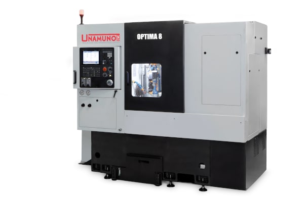
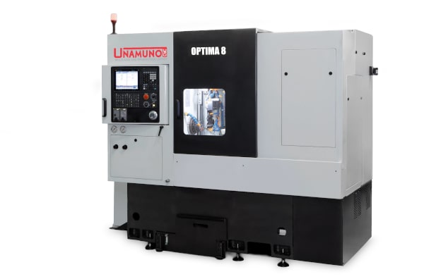
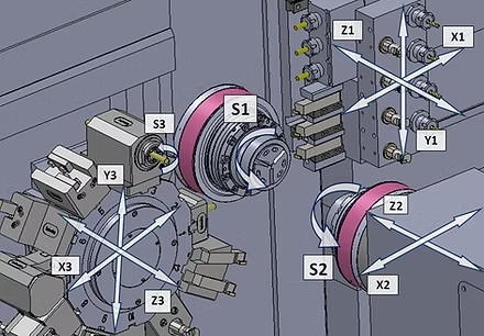
It features X-3, Y-3, and Z-e axes with a turret with no disc displacement during indexing, driven by a servo motor, with 24 stations for fixed or driven tools, with 12 for the main spindle and 12 for the sub-spindle.
It has X-1, Z-1, and Y-1 axes, as well as up 6 positions for exterior turning tools working on the main spindle 8 and positions for tools working on the sub-spindle.
Driven tooling system on both turret and tool comb.
Has two X-2 and Z-2 axes.
The "superimposition" feature of the control provides for simultaneously cutting with 3 tools to improve production cycles. With both the turret and the tool comb working on the main spindle, the turret can also work on the sub-spindle.
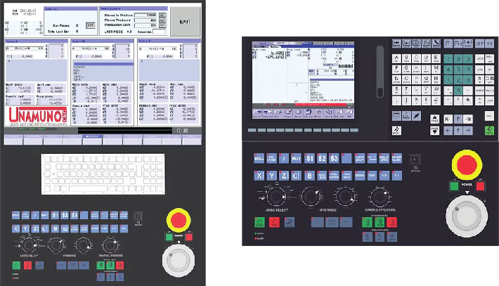
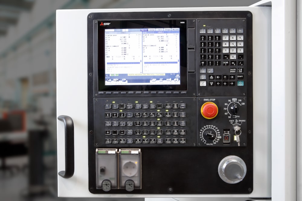
With the manual pulse generator, both the upper slide and the sub-spindle can be moved forward and backward with the programme. This feature considerably reduces machine fine-tuning times.
Additional standard control features:
| OPTIMA 8 | ||||
|---|---|---|---|---|
| Spindle | ||||
| Maximum round bar diameter at spindle | mm | 42 | ||
| Clamping system | Fixed position | HAINBUCH 42 DIN 6343 CHUCK |
||
| Main motor | ||||
| Main spindle motor power ED 100 %(50%) | kW | 7.5 (11) | ||
| Maximum spindle speed | rpm | 5000 | ||
| 2-axis sub-spindle | ||||
| Maximum round bar diameter for collet system | mm | 42 | ||
| Clamping system | Fixed position | HAINBUCH 42 DIN 6343 CHUCK |
||
| Sub-spindle power ED 100% (50%) | kW | 5.5 (7.5) | ||
| Maximum speed | rpm | 5000 | ||
| Maximum Z-2 axis travel | mm | 450 | ||
| Maximum Z-2 rapid traverse | m/min | 25 | ||
| Maximum X-2 axis travel | mm | 415 | ||
| Maximum X-2 rapid traverse | m/min | 20 | ||
| Cleaning coolant pressure | bar | 5 | ||
| 12-position, 3-axis front multi-tool turret | ||||
| Total number of tool positions with intermediate stops | Num. | 24 | ||
| Maximum number of fixed tools on spindle/sub-spindle | Num. | 12/12 internal or external | ||
| Tool clamping system | Type | BMT 45 | ||
| Tool bar size | mm | 20 x 20 | ||
| Internal tool holder with clamping diameter | mm | 25 | ||
| Maximum number of driven tools for spindle/sub-spindle | Num. | 12/12 axial or radial | ||
| Driven tool power | kW | 3.7 | ||
| Maximum driven tool speed | rpm | 4000 | ||
| Maximum X-3 axis travel | mm | 150 | ||
| Maximum X-3 rapid traverse | m/min | 20 | ||
| Maximum Y-3 axis travel | mm | 60 (+- 30) | ||
| Maximum Y-3 rapid traverse | m/min | 20 | ||
| Maximum Z-3 axis travel | mm | 150 | ||
| Maximum Z-3 rapid traverse | m/min | 25 | ||
| High pressure coolant | bar | 3 (up to 13) | ||
| 3-axis rear tool comb | ||||
| Total number of tool positions | Num. | 14 | ||
| Tool bar size | mm | 20 x 20 | ||
| Maximum X-1 axis travel | mm | 80 | ||
| Maximum X-1 rapid traverse | m/min | 20 | ||
| Maximum Y-1 axis travel | mm | 290 | ||
| Maximum Y-1 rapid traverse | m/min | 20 | ||
| Maximum Z-1 axis travel | mm | 100 | ||
| Maximum Z-1 rapid traverse | m/min | 25 | ||
| High pressure coolant | bar | 3 (up to 13) | ||
| OPTIONAL: Rear tool comb with driven tooling system | ||||
| Total number of tool positions | Num. | 11 fixed and 3 driven | ||
| Driven tool clamping system | Type | ER collet | ||
| Driven tool power | kW | 1.5 | ||
| Maximum driven tool speed | rpm | 5000 | ||
| Cooling system | ||||
| High pressure coolant supply | bar | 3 (up to 13) | ||
| Cleaning coolant supply | L/min | 100 | ||
| Tank capacity | L | 225 | ||
| Electrical requirements | ||||
| Machine voltage | V | 400 / 3 Phases | ||
| Transformer input voltage | V | Optional | ||
| Pneumatic supply | bar | 5/6 | ||
| Main dimensions | ||||
| Floor space (approx.) | mm | 3270 x 1690 | ||
| Total height | mm | 2212 | ||
| Weight (approx.) | kg | 6000 | ||