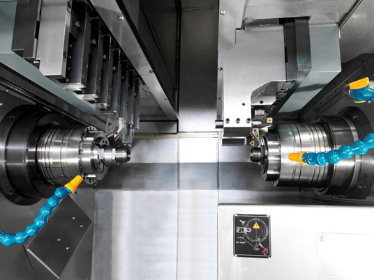
The machine provides two upper slides with tool combs, a three-axis left-hand slide for work on the main spindle and a two-axis right-hand slide for work on the sub-spindle.
The sub-spindle incorporates a Z axis which, in combination with the axes of the right-hand upper slide, allows a wider range of secondary operations to be executed.
The slide system with tool combs provide excellent versatility and extremely fast tool changes, while the Y axis provides a wide range of simultaneous turning and milling operations on both the main spindle and sub-spindle.
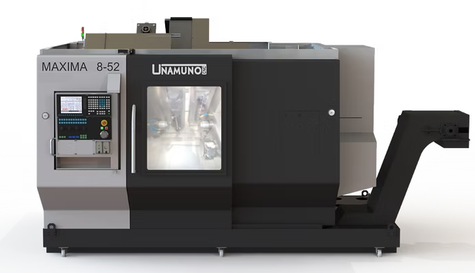
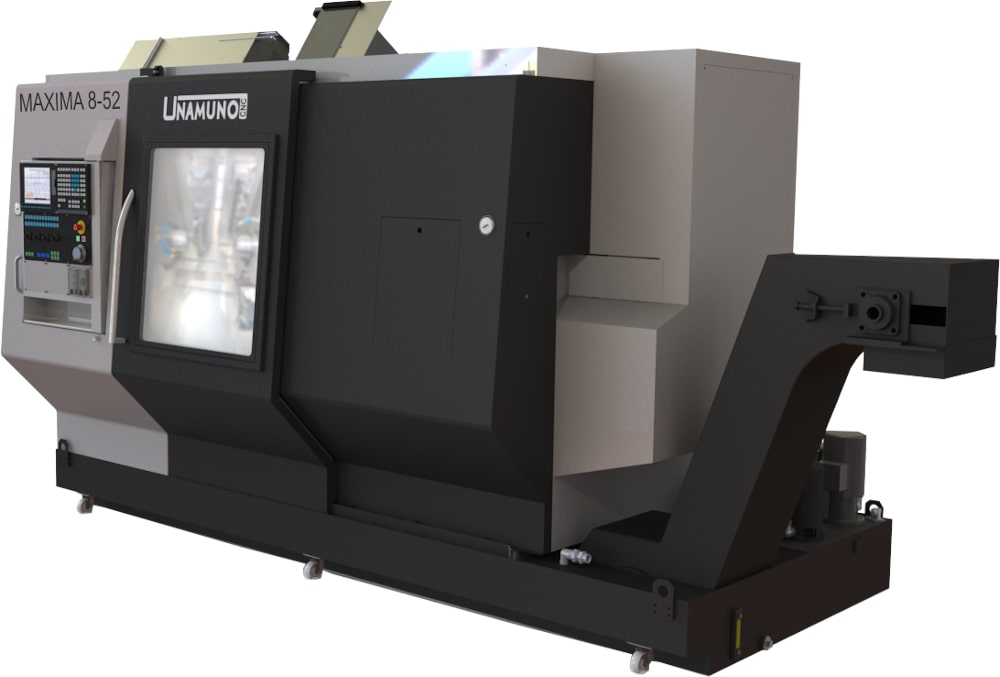
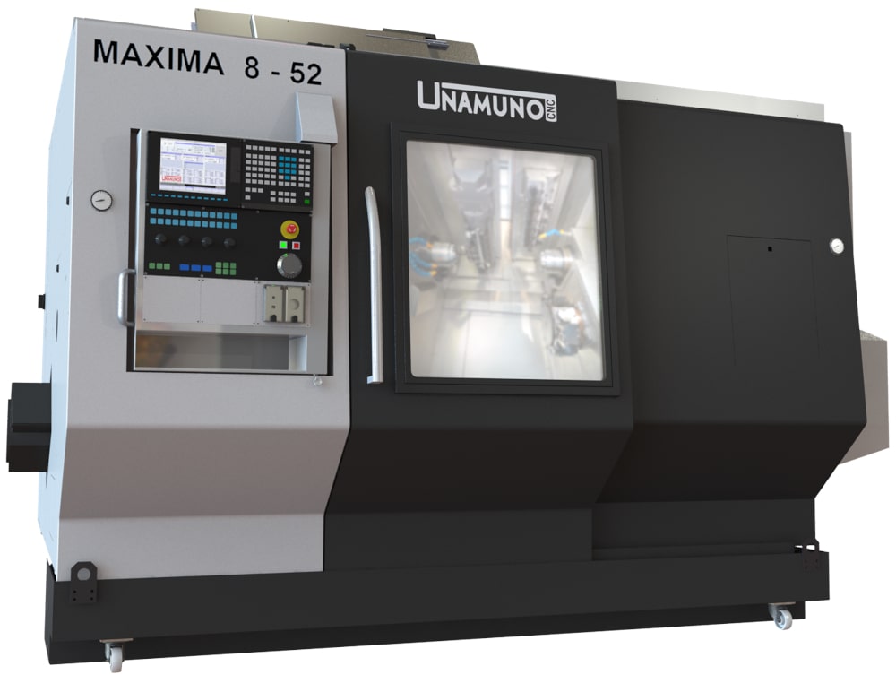
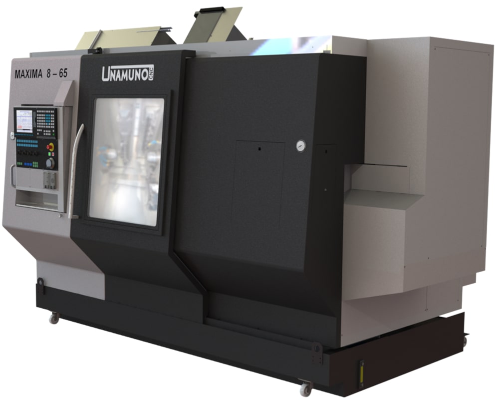
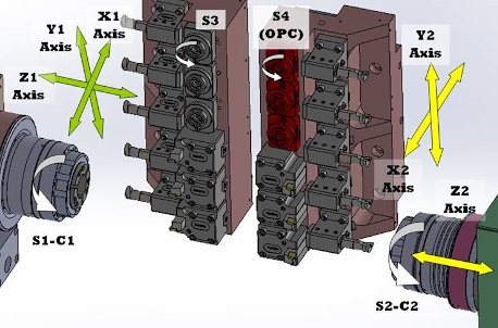
The left-hand upper slide with tool comb has X-1, Z-1, and Y-1 axes, as well as 11 tool positions, 5 fixed internal or external tools and up to 6 fixed or driven tools to work with the main spindle.
The right-hand upper slide with tool comb has X-2 and Y-2 axes, as well as 11 tool positions, 5 fixed internal or external tools and up to 6 fixed (or optional driven) tools to work with the sub-spindle (Z-2 axis on sub-spindle slide).
Z-2 axis.
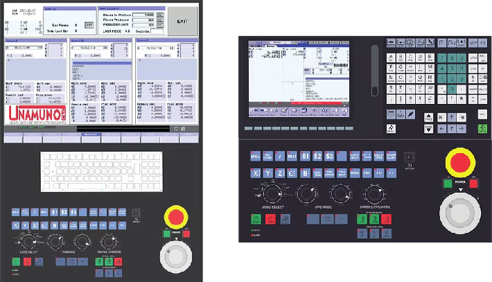
With the manual pulse generator, both the upper slide and the sub-spindle can be moved forward and backward with the programme. This feature considerably reduces machine fine-tuning times.
Additional standard control features:
| MAXIMA 8 | |||||
|---|---|---|---|---|---|
| Spindle | |||||
| Maximum round bar diameter at spindle | mm | 42 | 52 | 65 | |
| Quick-change collet system for spindle | Fixed position | HAINBUCH 42 | HAINBUCH 52 | HAINBUCH 65 | |
| Main motor | |||||
| Main spindle motor power ED 100 %(50%) | kW | 7.5 (11) | 11 (15) | ||
| Maximum spindle speed | rpm | 6000 | 5000 | 4000 | |
| Sub-spindle | |||||
| Maximum round bar diameter at sub-spindle | mm | 42 | 52 | 65 | |
| Sub-spindle through-bore | mm | 40 | 50 | 50 | |
| Quick-change collet system | Fixed position | HAINBUCH 42 | HAINBUCH 52 | HAINBUCH 65 | |
| Spindle sub-spindle motor power ED 100% (50%) | kW | 3.7 (5.5) | 5.5 (7.5) | 7.5 (11) | |
| Maximum speed | rpm | 6000 | 5000 | 4000 | |
| Maximum Z-2 axis travel | mm | 750 | |||
| Maximum Z-2 rapid traverse | m/min | 30 | |||
| Extraction system pressure for coolant blow-off | bar | 5 | |||
| Air-blow tank | L | 15 | |||
| Left upper slide | |||||
| Total number of tool positions (main spindle) | Num. | 11 | |||
| Row 1: Maximum number of fixed tools | Num. | 5 internal or external | |||
| Row 2: Maximum number of fixed or driven tools | Num. | 6 external | |||
| Tool bar size | mm | 20 x 20 | |||
| Internal tool holder with diameter | mm | 32 | |||
| Optional: Clamping system for driven tools | Type | ER | |||
| Optional: Clamping system for driven tools | kW | 5 (constant) / 8 (peak) | |||
| Optional: Driven tool torque | Nm | 16 (constant) / 26 (peak) | |||
| Optional: Maximum driven tool speed | rpm | 4000 | |||
| Maximum X-1 axis travel | mm | 260 | |||
| Maximum X-1 rapid traverse | m/min | 20 | |||
| Maximum Y-1 axis travel | mm | 420 | |||
| Maximum Y-1 rapid traverse | m/min | 20 | |||
| Maximum Z-1 axis travel | mm | 200 | |||
| Maximum Z-1 rapid traverse | m/min | 30 | |||
| High pressure coolant | bar | 9 | |||
| Right upper slide | |||||
| Total number of tool positions (sub-spindle) | Num. | 11 | |||
| Row 1: Maximum number of fixed tools | Num. | 5 internal or external | |||
| Row 2: Maximum number of fixed or driven tools | Num. | 6 external | |||
| Tool bar size | mm | 20 x 20 | |||
| Internal tool holder with diameter | mm | 32 | |||
| Optional: Clamping system for driven tools | Type | ER | |||
| Optional: Clamping system for driven tools | kW | 5 (constant) / 8 (peak) | |||
| Optional: Driven tool torque | Nm | 16 (constant) / 26 (peak) | |||
| Optional: Maximum driven tool speed | rpm | 4000 | |||
| Maximum X-2 axis travel | mm | 260 | |||
| Maximum X-2 rapid traverse | m/min | 20 | |||
| Maximum Y-2 axis travel | mm | 420 | |||
| Maximum Y-2 rapid traverse | m/min | 20 | |||
| High pressure coolant | bar | 9 | |||
| Cooling system | |||||
| Total number of coolant pumps | Num. | 4 | |||
| Pump 1. High pressure coolant supply | bar | 9 | |||
| Pump 2. High pressure coolant supply | bar | 9 | |||
| Pump 3. Work cleaning area | L/min | 100 | |||
| Pump 4. Chip extractor drum filter cleaning | bar | 4 | |||
| Tank capacity | L | 380 | |||
| Power requirements | |||||
| Machine voltage | V | 400 / 3 Phases | |||
| Transformer input voltage | V | Optional | |||
| Total power requirement | kW | 35 | |||
| Pneumatic supply | bar | 5/6 | |||
| Main dimensions | |||||
| Floor space (approx.) | mm | 4475 x 2375 | |||
| Total height | mm | 2400 | |||
| Weight (approx.) | kg | 9000 | |||